For the standard ruthex RX-M3x5.7, the manufacturer specifies a 4.0 mm installation hole. That is not a promise that a 4.0 mm CAD hole will print correctly on your machine. Start from the drawing, print a small diameter ladder, and check seating and retention. Other M3 insert geometries can need a different hole.
ruthex hole-size chart: exact standard-length parts
These are manufacturer reference dimensions, not CAD compensation values. The table transcribes hole diameter d3, insert length L and minimum radial wall W from the ruthex size drawing. Match the part name using the manufacturer’s CAD directory; short and VORON variants are not interchangeable with these rows.
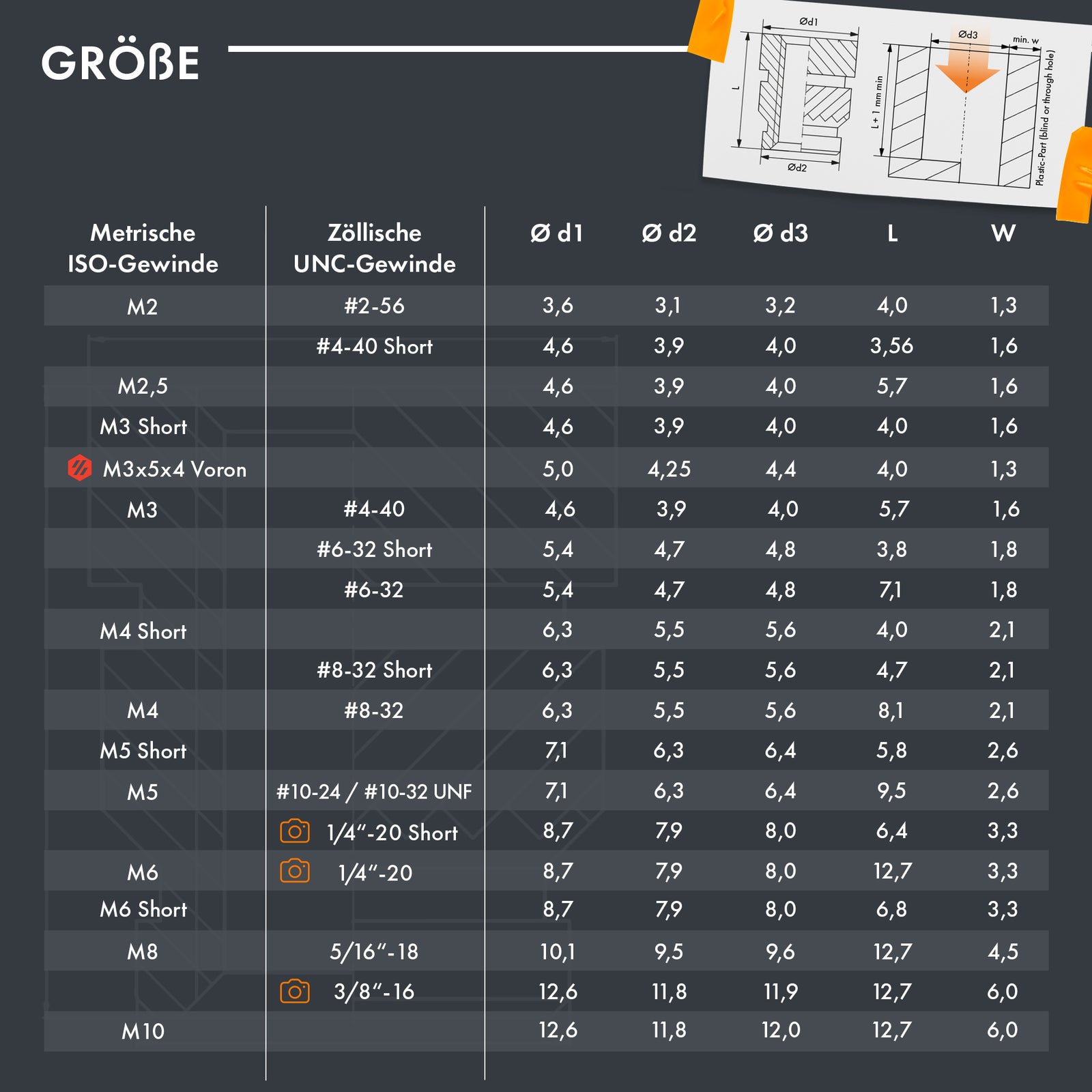
| Exact part | Hole d3 | Length L | Min. wall W |
|---|---|---|---|
| RX-M2x4 | 3.2 | 4.0 | 1.3 |
| RX-M2.5x5.7 | 4.0 | 5.7 | 1.6 |
| RX-M3x5.7 | 4.0 | 5.7 | 1.6 |
| RX-M4x8.1 | 5.6 | 8.1 | 2.1 |
| RX-M5x9.5 | 6.4 | 9.5 | 2.6 |
| RX-M6x12.7 | 8.0 | 12.7 | 3.3 |
| RX-M8x12.7 | 9.6 | 12.7 | 4.5 |
The diagram also calls for at least L + 1 mm depth. Check the current drawing supplied with your parts before design release. These dimensions describe this supplier’s series; they are not an ISO heat-set hole standard.
In ruthex’s same drawing, the M3x5x4 VORON version has a 4.4 mm hole recommendation, versus 4.0 mm for RX-M3x5.7. Thread size identifies the screw, not the outside shape of the insert. A tap-drill size is a different dimension again.
Supplier differences matter even when part names look similar: CNC Kitchen’s current chart gives 5.7 mm for its M4×8.1, while the ruthex row above gives 5.6 mm. Use the drawing for the insert actually in your hand. See the CNC Kitchen dimensions PDF.
Keep these three diameters separate
- Supplier hole dimension: the installation-hole reference for a named insert. Start here.
- CAD hole dimension: what you draw and export. A slicer or CAD correction may make this larger than the supplier reference.
- Printed hole dimension: what you measure on the cooled part before installation. This, together with the installation process, determines how the insert seats.
Do not compare a compensated CAD diameter directly with the brass knurl diameter and conclude that the insert cannot grip. They describe different stages. Equally, do not assume a pilot diameter measured from a STEP file is the recommended hole: the drawing distinguishes those dimensions.
M3 example: from a 4.0 mm reference to a first CAD trial
Calculated example, not a print result. Suppose you have RX-M3x5.7 and use this site’s starting PLA profile: 0.4 mm nozzle, 0.2 mm layer, 0.45 mm line width, 0.3% assumed shrinkage and default hole coefficient 0.5. Treating the supplier’s 4.0 mm hole as the target gives:
CAD trial = (4.0 + 0.3675) ÷ (1 − 0.003) = 4.381 mm
This is a heuristic starting estimate, not ruthex’s recommendation and not a demonstrated optimum. A tuned printer may need substantially less correction. If you already have local measurements, use those rather than this default.
Open the M3 / 4.0 mm target example →Pre-fills PLA, hole-only, hole datum, zero fit clearance, 0.4 mm nozzle and all assumptions above. Read the hole result; this does not model a heat-set joint’s strength.Use a hole-only target with zero extra fit clearance for this sizing exercise. Selecting a generic press fit does not calculate the interference needed by a knurled heat-set insert. Its anchoring comes from the installed geometry and surrounding material, which the fit solver does not simulate.
What an actual published experiment found
CNC Kitchen tested its own M3 inserts using a CORE One L and PolySonic PLA. On that setup, printed holes were about 0.25 mm smaller than CAD; a 4.2 mm CAD hole offered easier seating while retaining roughly 90% of the maximum pull-out strength measured in the experiment. This is useful evidence that installation quality and peak strength can trade off, but it does not validate our 4.381 mm estimate or prescribe an offset for ruthex. Read the original experiment and its test conditions.
Evidence status: what this page knows
This guide combines three evidence types. Keeping them separate matters: a supplier drawing tells you what part was specified, a published experiment tells you what happened on one other setup, and the calculator produces a repeatable estimate. None of those is a physical test by MachinistCalcs.
| Evidence | Used here | Boundary |
|---|---|---|
| ruthex drawing | RX-M3x5.7: 4.0 mm installation hole, 5.7 mm insert length, 1.6 mm minimum radial wall. | Supplier reference for that exact part family; not a universal M3 standard and not a printed result. |
| CNC Kitchen experiment | CORE One L, PolySonic PLA, roughly 0.25 mm smaller printed holes; a 4.2 mm CAD hole and about 90% of measured maximum pull-out strength in that test. | External experiment with different inserts, machine and profile; it does not validate ruthex or this site’s default coefficient. |
| MachinistCalcs calculation | 4.381 mm CAD starting estimate from the stated nozzle, layer, line width and shrinkage assumptions. | Calculated example only. No MachinistCalcs printer, cooled-hole measurement or pull-out test is being claimed. |
| MachinistCalcs physical validation | Not available yet. | Requires a labelled diameter ladder, printer settings, cooled measurements and installation results. |
Use the external experiment as a reason to test a range around the supplier dimension, not as a number to copy. Once a reader supplies a reproducible test record, it can be added as a separate dated case study without rewriting the source table or mixing it into the calculator default.
Print a diameter ladder before the enclosure
- Choose the exact insert and profile. Keep material, orientation, walls, infill and slicer compensation the same as the final boss.
- Make several labelled holes. For a first RX-M3x5.7 trial, a CAD ladder such as 4.0, 4.1, 4.2, 4.3 and 4.4 mm brackets the example above. This is an exploratory test range, not five approved designs. Refine around the best result or extend the range if none works.
- Measure before heating. Record each CAD value, cooled bore measurement and print settings. Keep those measurements separate from your installation notes.
- Install consistently. Use the insert supplier’s temperature and tooling guidance, keep the axis straight, and let each sample cool before evaluation.
- Check the assembled joint. Inspect for burrs, cracks, tilt and movement; verify the screw can travel freely without bottoming. Repeat the chosen size and test it under the intended assembly load.
CNC Kitchen publishes a downloadable insert-hole test set for its inserts. Choose the matching variant; inspect its geometry and dimensions before using it with another brand. Its installation guide explains orientation and burr checks. For a general printer baseline, use our 20 mm bore-and-peg coupon; it does not replace an insert-sized boss test.
Download a blank CSV measurement log. Put the insert part number, iron setting, seating behaviour and screw/load checks in the notes column. No example measurements are pre-filled.
Boss walls, depth and installation
For RX-M3x5.7, the ruthex drawing above lists a 1.6 mm minimum wall and at least 6.7 mm hole depth. Interpret these with the drawing’s cross-section, and preserve the wall when changing the CAD hole. More depth may be needed for the screw and tool; the screw must not bottom out and push the insert upward.
Do not replace the supplier’s boss requirements with a universal “wall = one quarter of the hole” rule. Supplier guidance varies: SPIROL’s insert design guide discusses material, boss geometry and screw jack-out, and uses different depth guidance for its products. An FDM boss also needs validation with its actual layer orientation and load direction.
Use a controlled, repeatable installation process. Allow the plastic to soften rather than forcing a cold insert into an undersized bore; avoid moving the insert while the surrounding material cools. There is no single iron temperature that this article can prescribe for every PLA, PETG, tool and insert mass. Follow the selected supplier’s instructions and record the setting used for your coupon.
Troubleshooting
| Observation | Check next |
|---|---|
| Insert will not pre-seat | Confirm the part and hole reference; measure the opening. Check first-layer constriction or a sagging horizontal bore before enlarging every hole. |
| Plastic burr blocks the screw | Inspect the underside, installation depth and heat. Try the next larger test hole while keeping the other settings fixed. |
| Insert spins or pulls out | Check oversized bore, incomplete seating, insufficient surrounding material and overheating. A visually flush insert is not a strength test. |
| Boss cracks or distorts | Recheck wall geometry, orientation, hole size and installation force. Repeat on a representative boss, not just a thin flat coupon. |
| Screw becomes tight near the bottom | Check screw length, bottom clearance and displaced plastic before applying more torque. |
Can M2 inserts work with a 0.4 mm nozzle?
A nozzle diameter alone does not establish impossibility. The relevant checks are the printed bore, surrounding walls and installation outcome. Use the RX-M2x4 drawing and test a representative boss; the model becomes less reliable on small features.
Can I use the same CAD hole in PLA and PETG?
Keep the exact insert’s reference drawing, but re-test the CAD correction and installation process when you change material or profile. A material dropdown cannot establish that two prints will have the same dimensions or joint strength.
Should I drill the hole first?
A drilled sample is a useful separate process to test. Record the measured result and inspect the remaining boss; do not apply an as-printed CAD offset again after drilling to size. Compare installation and retention before adopting it.
Revision note: this update replaces STEP-derived hole guesses with the manufacturer’s d3 values, corrects the M4/M6/M8 reference holes, includes shrinkage in the worked CAD example, and removes the unsupported M2/nozzle impossibility claim.